
Coding BIM projects
Introduction
One of the main objectives of the BIM methodology is to centralise and share project information. In order to ensure a correct exchange, it is essential to establish classifications that allow for an accurate identification, not only of the elements within the models, but also of the external documentation to be shared. For this purpose we use codes or codification systems.
In this post we’ll focus on some considerations when coding elements in a BIM project.
What is codification?
When we talk about codification, we refer to the registration of information by means of a code as a result of a combination of letters, numbers or other characters that follow a system. This set of characters define the element that the code refers to and enables its identification, thus easing the search for information within a system.
A code can relate to different element properties, and can be used in two different ways depending on whether the code is included in the name (naming), or stored in element parameters or attributes.

Naming
This is the most general level of coding. One typically applies a codified naming convention to documents and folders, specially in a Common Data Environment (CDE), so the name helps identifying several properties of the file or folder without relying on metadata. Document and folder naming generally conveys properties that are immutable or subject to little change, with other, more dynamic attributes like versions, dates or status being captured, preferably, in metadata.
Parameter Coding
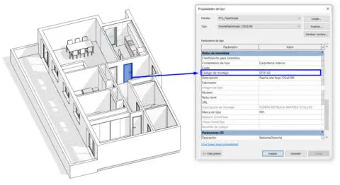
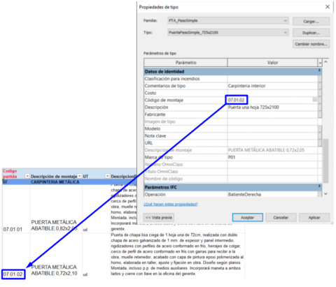
At a more specific level within a BIM model, apart from the name of an element, one can provide additional information by adding codes into a specific parameter. Parameters are usually dedicated to different functions. For instance, the parameter “Assembly code” is commonly used to establish a relationship between the model elements and quantity take off items, as we see in the image below. It relates the model elements to their price lines in a direct way. So, the “Assembly Code” of a door in our Revit model could be “07.01.02”, giving information about its identification and detailed location within a structure of budget chapters and subchapters.
Why is coding important?
The benefits of coding in the project are many:
- Identification of each element in a clear way.
- Identification of the elements without the need to consult their internal properties.
- Use of a single common language for all project members.
- More efficient search and filtering of information.
- Order and structure of the elements.
- Storage of summarized information in models or other documents.
- Linking elements with databases.
Naming systems
It is common to use naming conventions to organise information in complex environments. These conventions are based on the concatenation of fields represented by sets of alphanumeric characters. These may refer to a given classification or to a hierarchical structure, and their length is recommended to be invariable. Coding systems may be human or reader friendly, with their parts being meaningfully linked to the represented attributes, or just machine friendly, using sequences that have no straight connection with the underlying item.
Compare these two codes:
MOD-3DM-Z-00001
001.002.1.00001
They may convey the same information but with a bit of context the former is easier to read and remember.
When incorporating these characters as combinations of letters or fields relating to descriptions with texts, we define a specific writing style (uppercase, lowercase, UpperCamelCase, etc). We also recommend avoiding marks, spaces, symbols and accents, as they are sometimes not handled well by certain platforms or languages.
The concatenated fields may be linked with separators such as hyphens or periods (“-“, “_”, “/”, “.”, etc) and one generally sets them from general to specific, in order to facilitate their comprehension. The result is a code that at a first sight gives information about different aspects of the element.
The fields based on characters always follow defined tables that provide sets of valid characters to add in the code. As an example, a field “Discipline” for BIM documentation could, follow a table like this:
| Discipline | Field value |
| Architecture | ARC |
| Structure | STR |
| General | GEN |
| Facilities | FAC |
| Landscape | LAN |
| Not applicable | XXX |
| Multiple | ZZZ |
It should be noted that it is possible for the field to be filled with character sets that are not defined in the table. If so, one has to consider adding that new set to the table if it makes sense or try to assign it to the existing ones.
Although we are free to define a specific naming convention applied for particular standards, the order in the collaborative environment should not be altered; it is important to know, understand and follow pre-established systems when we join new projects. The knowledge of common naming conventions, such as those established in ISO 19650 National Annexes, can be useful to set up your own coding system for the general nomenclature of each document. The UK ISO 19650 National Annex provides an example of fields combination that establishes a nomenclature system..

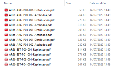
Documentation naming
When we use a code in the name of documents it is key to identify which fields will be useful in the project so as to order them correctly. We must consider multiple cases given the documentation generated throughout the construction project is varied, from drawings and BIM models to area tables and cost plans. Below are some of the most common fields to consider for document names:
- Project code: project identifier code.
- Author: document generator.
- Phase: phase in the construction project.
- Volume or system: blocks, zones or groups.
- Identifying type of document: typology of the document.
- Identifying subtype: second level of classification of the document typology.
- Discipline: scope of the document.
- Sub-discipline: second level of classification of the document scope.
- Level: below/above ground or specific floor.
- Sequential number: identifying number.
- Revision: version of the document.
- Status: status of the document.
- Description: brief definition of the document.
Below is an outline of a general example encoding structure for the name of a specific document:

Some CDEs such as ACC, BIM360 or ProjectSight enable the automatic recognition of document name fields according to pre-established naming standards. This can be very useful for adding information as metadata, which will then allow us to sort and filter the documents. This is one of the reasons why it is important to respect the length of the fields and use the separator established in the system.

Folder naming
In order to name the folders of the project it is essential to take into account the environment in which we are working. On the one hand, it is important to follow a standard in the folder naming in the internal server where the project is hosted. Each of them must incorporate a consistent code in a name that make it possible to recognise the documentation it stores. There are many options, and a common criterion is to incorporate a sequential number to put them in alphabetical order, especially in those projects with the same typology. As an example, a possible base folder structure to work on BIM projects could be: 01_Documentation, 02_Plans, 03_Measurements, 04_BIMModel, etc.
The most usual values which allow us to organise the information and to filter it quickly are the “author” and the “date”. Including a brief description of the subject or content can be useful too, although this field can be very different in each folder. Considering the above, a name for a folder that includes photographs taken on site on a specific day could be:

BIM model elements naming (Revit)
It is a good practice that the elements within the BIM model have a naming that eases their identification and organisation. Below we explain the most important ones.
Families and types
Specifying a name that helps recognising each element of the geometry of the model will be key. Sometimes we use abbreviated prefixes identifying the categories related to the families; this is quite useful when exporting the models and working with them in other softwares, as it provides information of the element’s nature. On other occasions, we incorporate the team responsible for the model or the project code as a prefix to the name in order to identify the specific families that were created for that model. As for the types of families, we often specify typological differences by means of descriptions and a pre-established criterion; as an example for a window:
Category_DifferenceTypology1_DifferenceTypology2
WIN_1500x750mm_TwoPanels_Sliding.rfa
Worksets
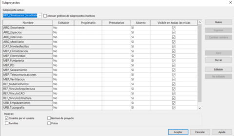
In the case of worksets, it is essential to use a criterion that differentiate the discipline (architecture, structure, facilities,…), and establishes codes that will ensure their recognition and correct management between linked models.
An example for the plumbing fixtures workset could be MEP_Sanitary. We will be able to recognise all the worksets dedicated to systems at a first sight thanks to the identifying prefix MEP.
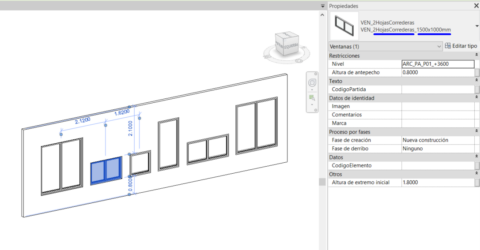
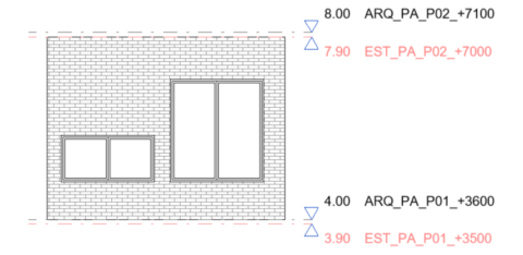
Levels
In the same way as the worksets, coding the levels of the model is fundamental. The coded level name should include the discipline and the elevation to which it refers. This information is particularly useful in elevations, sections and 3D views. An example for the structural level of the second floor in plot A:
Discipline_Volume_Floor_Height.
STR_PA_P01_+3600m
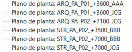
Views and schedules
Regarding the work in progress views and schedules, it is convenient to set naming codes that allow for recognition of the user who is working in a particular view. This is usually achieved by adding by the acronym of their name (incorporating the discipline as in previous cases) to avoid the inappropriate use of them. An example for the architectural view on the second floor in plot A, by user JCG:
Discipline_Volume_Floor_Height_User.
ARQ_PA_P01_+3600_JCG
Parameter coding systems
There are multiple international classification standards. Some of the most common systems that use parameters to include an identifying code in the BIM model are Uniclass, Omniclass, Uniformat or SfB.
Uniclass, created in the UK, is one of the most widely used in Europe and is also defined as a table-based method according to a hierarchy, so that each element of the model is given a code as a concatenation of fields referring to groups, subgroups and sections. An example of coding for foundations according to Uniclass 2015 could be “EF_20_5_30”.

Similarly, the Omniclass classification system, developed in the United States, is also based on a series of digits concatenated and sorted by tables. In this particular case for foundations, according to table 21, the identifying code could be “21-01 10 10”.

This shows that there are multiple ways of coding an element depending on the system we are using.
We are free to develop our own classification system according to the needs of the project. We could consider specific code systems for Facility Management asset identification, 4D planning, budgets, etc.
If we prefer to define our own coding rules, it is a requirement that they are written down in the BEP, so that there is a record that is accessible to external users or new team members who are not familiar with the system. In addition, the document will serve as a dictionary that defines the values of the characters in use, so its consultation will be essential when coding.
As we have done with naming systems, we detail the most important elements to be coded below.
Codes in model elements parameters
Depending on the information and the use of our BIM model, we choose to give the code in one parameter or another following defined criteria. Some of the uses that mark the coding of the geometry of the model are:
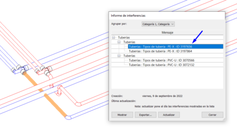
Element identification for coordination purposes
The ID is assigned directly by Revit and is not editable. If we modify an element, the ID is maintained, but if we delete it and recreate it the ID will be different. Each element of a model incorporates a unique ID that enables the identification of the element. This can be especially useful in clash detection.
Scheduling (4D BIM)
Adding codes in parameters related to the planning of the construction project allows to control the development of the project in real time.
Estimating (5D BIM)
We can link items from budget documents to model elements using parameters that include codes that save time in quantity take-offs.
Sustainability (6D BIM))
The use of codes in parameters related to sustainable certifications allows us to identify elements that compute for specific criteria and transfer their data to certification tools.
Facility Management (7D BIM)
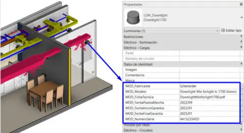
Coding the geometry of the model by including codes in parameters that define the manufacturer of each element, model, technical data sheets, installer, maintenance frequency, etc., is useful for the control and management of assets in as-built models attending to facility management.
MEP systems
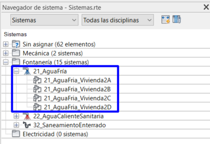
Coding MEP systems is key when formulating them in the system browser. One possibility is to arrange the system types according to a recognisable numerical prefix that orders the system discipline in our projects and that can be defined in the “System abbreviation” parameter. We can obtain system types such as 20_Plumbing, 21_CoolWater, 22_SanitaryHotWater, 30_Sanitation, etc, so that we are taking into consideration that prefix identifier and the type name. This is quite useful when identifying the plumbing discipline (20) and its derivatives such as cold water and hot water with correlative numbers in the series of 20, i.e. 21, 22, etc.
In addition, the name of the system can include, concatenated as a field at the end of the code, the specific “network” it belongs to, for example 21_Cold_Water_Unit2D.
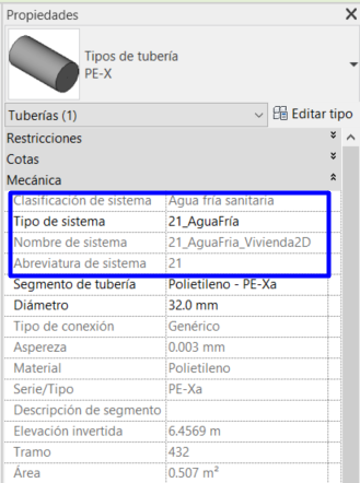
The goal is to establish a connection between the elements that make up the system and the coding that we include in its parameters, thus making the network recognisable. If we neglect codes in MEP parameters, the model can be very difficult to manage.
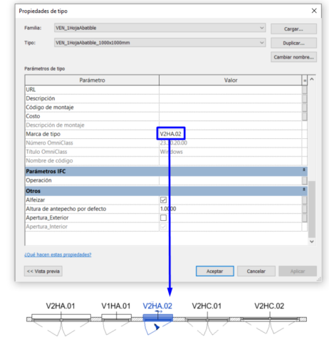
Plan annotations
In order to avoid manual labelling of modeled elements, we can include this information in their own parameters, making each of them a container of the information. The tag we use in BIM models can read the element parameter, which is much more agile to manage if that information needs to be updated. In addition, if we include these parameters in the types, we further reduce the workload.
Codes in space parameters (areas and rooms)
Accurate coding of the areas and rooms in the model will enable any area takeoffs and automated filling of fields in area tables. In residential projects, it is common to identify these areas by coding parameters such as the name, the type of area or the dwelling identification (door, floor, number, typology, etc). This allows for the storage of the information and automatic process of the different areas needed in the project without being calculated in external platforms or manually from plans. In addition, from a business approach, we have the possibility of extracting stacking plans easily enabling the 3D views of the areas and reading its own parameters.
Furthermore, taking into consideration energy aspects, spaces coding facilitates the estimation of thermal or lighting demands, since it allows assigning to the project rooms, according to their type, parameters such as the ratio of air changes per hour, the luminous intensity per square meter or occupancy schedules, among others.
Additionally, asset management oriented models should include, codes for space parameters that will provide real time information on some aspects such as, the status of the rooms (rented, sold, etc.) or the tenants.
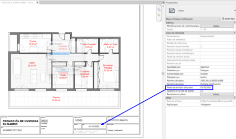
Codes in sheet parameters
Sheets are also key elements when coding within the BIM model, which usually store information such as the drawing view, number, author, date, plan version, among others. BIM software allows us to include that information in parameters, updating them easily and filling them in batches or even by reading information from the views it contains and, in some cases, automatically. For specific data such as the sheet issue date, we have the possibility of modifying multiple “sheets” (drawings) at once managing the value of its parameters so that its title block is automatically updated.
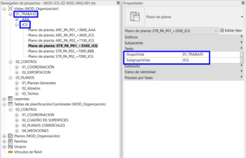
Codes in view and schedule parameters
Lastly, Revit gives us an option to sort the project browser according to view and schedule parameters. To achieve “goog” model organisation we consider parameters that help us to sort by groups (01-WORK, 02-CONTROL, 03-SHEETS, etc) and subgroups (01-Floors, 02-Elevations, 03-Ceilings…), discipline (ARC, STR, MEP), author, etc.
Conclusions
So far we have seen a few examples of how to code in and out the BIM model. As we have mentioned, it is essential to consider the approach we are taking to our work and to be clear about the desired result. This is the reason for choosing our coding system and the elements that will be part of it. There are many ways of coding and all of them can be valid as long as they are consistent: the main thing is that they fit the needs of our project. Here are some tips to keep in mind that we find useful when using codes:
- Writing codes with names that are too long can be tedious for those involved in the project and can also cause problems in terms of storage when the location path is too long on the server.
- We cannot forget that each team involved in the project works locally with its own nomenclature, so we must carefully select which documents must follow a strict naming convention and which can be given some flexibility.
- It is preferable to establish well-defined nomenclatures trying to consider as many possibilities as possible to avoid doubts and mistakes when coding.
- There are nomenclature checkers in some collaborative environments such as BIM360, ProjectSight, Aconex, etc. We can use them to ensure that the documentation is following the defined system.
- A common mistake when coding is the repetition of a code that should be unique in several elements. It is important to pay special attention when coding, particularly with regard to parameters within the BIM model. Schedules can be used if necessary. There is also the possibility to give the code by exporting the parameters to external software such as Excel, filling them in there and bringing them back to the model.
References
EN ISO 19650-1 – Organization and digitization of information about buildings and civil engineering works, including building information modelling (BIM)
Building Smart – Manual de Nomenclatura de Documentos al utilizar BIM. Junio 2021.